Korean Nuclear Industry
- APR1000
-
European Standard Design
The APR1000 is a medium capacity Gen III+ Pressurized Water Reactor(PWR), generating 1,000 MW of electrical power to comply with up-to-date international safety requirements.
To enhance plant safety with excellent performance, the APR1000 is based on the proven design and operating experience of the OPR1000 and the APR1400.
APR1000 Major Parameters
GENERAL
PLANT DATAGross Power Output 1,050 MWe Thermal Power 2,825 MWth Design Lifetime 60 years Seismic Design Basis DBE 0.3g REACTOR
COREActive Core Length 3.81 m Core Diameter 3.124 m Average Heat Flux at 100% Power 589.1 kW/m2 Number of Fuel Assemblies 177, 16×16 Fuel Cycle Length 12 to 24 months REACTOR
COOLANT
SYSTEMNumber of Loops 2 Operating Pressure 15.5 Mpa Inlet Temperature 295.8℃ Outlet Temperature 327.3℃
- Enhanced Safety
-
Safety Requirements & Targets
Incorporates latest IAEA-WENRA-EUR safety requirements
- As well as a code of federal regulations and regulatory guidelines of U.S.

Safety Design Requirements
Established safety targets in accordance with IAEA SSR-2/1
Set to meet CDF target 〈 1 x 10 -5/RY, LRF target〈 1 x 10 -6/RY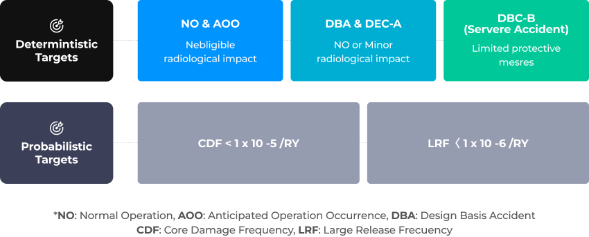
Practical Elimination(PE) of Large or
Early Radioactive ReleasesProvides appropriate design provisions for 10 phenomena based on
latest IAEA-WENRA-EUR safety requirements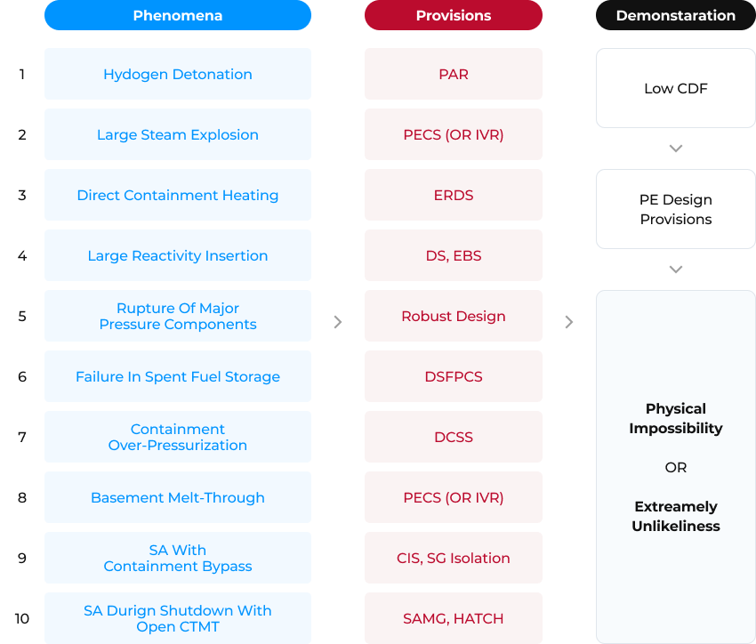
Concept of Demonstration of Practical Elimination
7 Day Autonomy of Safe Shutdown for AOO,
DBA and DECProvides sufficient/extended autonomy(with respect to operator actions & external supply) & No need to use non-permanent equipment until 7 days for all plant states
Only the safety classified & permanent systems are used to achieve below targets


1) SC-2 if the consequence of tis failure is of ‘medium’ severity
2) SC-3 if the consequence of tis failure is of ‘medium’ severity
3) SC-2 if it provides a backup of SC-1 function
Autonomy Design Concept
- Advanced Design
Features -
Safety Systems for Design Basis Accident(DBA)
Safety Injection System (5IS)
- 4 independent trains
- Provide borated water to core with active & passive components
- Fluidic device installed at the bottom of the Safety Injection Tank (SIT) passively and efficiently controls the safety injection flow into the core
Shutdown Cooling/Containment Spray System (5C5/CS5)
- 4 trains both for 5C5 and CSS
- 5C5 removes decay heat from core
- C55 reduces containment pressure and removes fission products
Passive Auxiliary Feedwater System (PAF5)
- Removes decay heat to reach shutdown cooling entry condition
- Provides an independent means of passively returning condensate to the steam generator by using gravity force in the events where the MFW5 is unavailable
Spent Fuel Pool Cooling System (5FPC5)
- Removes decay heat from spent fuels during normal operation
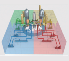
4 Train Safety Injection System
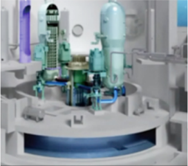
IRWST
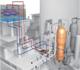
PAFS
Double Containment Building
Primary Containment Structure
- Keep the pressure boundary by liner plate
- Provide biological shielding & reduce the radioactive release
Secondary containment structure
- Fully envelop the primary containment
- Preserves structural integrity against airplane crash
- Secondary containment HVAC system
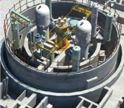
Double Containment Building
Safety Features for Design Extended Condition(DEC)
Emergency Boration System (EBS)
- Injects highly concentrated borated water into RCS through 4 DVI nozzles for diverse reactor trip
Diverse Containment Spray System (DC5S)
- Controls containment pressure & removes fission products from the containment atmosphere during severe accidents
- Diverse shutdown cooling in case of loss of RHR
Diverse Spent Fuel Pool Cooling System (DSFPCS)
- Provides Diverse Spent Fuel Pool Cooling System for loss of spent fuel pool cooling
Emergency Reactor Depressurization System (ERD5)
- Reduces the RCS Pressure before reactor vessel breach to prevent HPME
Passive Ex-Vessel Corium Retaining & Cooling System (PECS)
- Retains & cools down the Ex-Vessel Corium after vessel failure with Core Catcher
- Operated passively by gravity force
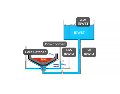
PECS
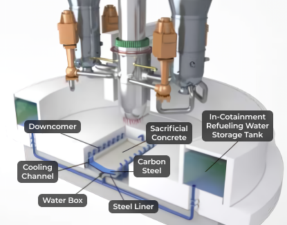
Core Catcher
Passive Autocatalytic Recombiner (PAR)
- Limit hydrogen concentration
- Prevent hydrogen detonation
Aircraft Crash Protection Design
- Secondary containment provides barrier against a large, commercial aircraft crash
- Strengthened external wall of the containment building & auxiliary building *Separation of other safety important buildings
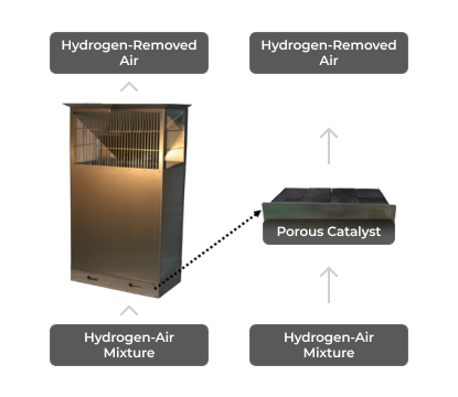
PAR
Diverse Safety Features
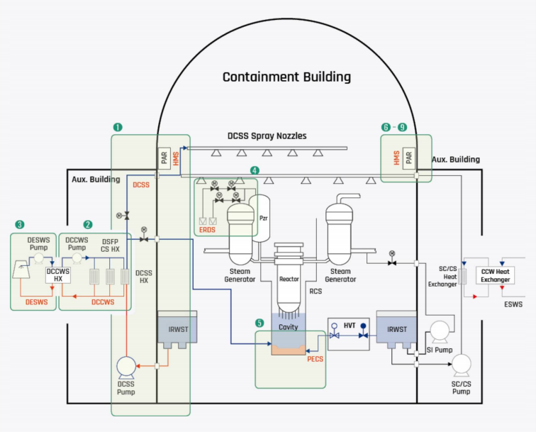
- ODCSS : Diverse Containment Spray System
- ©DCSWS : Diverse Component Cooling System
- ©DE5W5 : Diverse Service Water System
- OERDS : Emergency Reactor Depressurization System
- ©PECS : Passive Ex-vessel Corium Retaining and Cooling 5ystem(Core Catcher)
- ©HMS : Hydrogen Mitigation 5ystem
- ODECWS : Diverse Essential Chilled Water System
- ODSFPCS : Diverse Spent Fuel Pool Cooling System
- OPAR : Passive Autocatalytic Recombiner
- Excellence in
Construction -
Top-Down Method
Use the top-down method with large capacity cranes to reduce the construction period
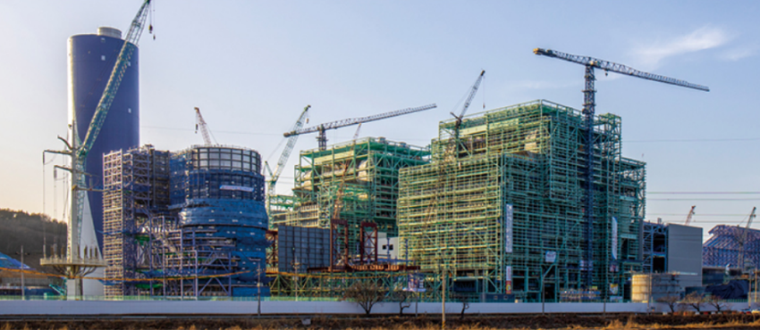
Large Capacity Cranes
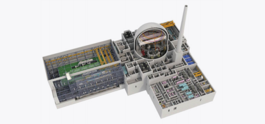
IT-Based Real Time Virtual Construction Management System
Utilize Accumulated Knowledge Adequately throughout Design, Construction & Operation Phases, etc.
Main Function is to Consistently Manage Information to Evolve the Construction Work to Process-Based Work
- To Further Implement with the Owner’s Plant Cycle Management
- Outstanding
Performance -
Convenient Operation & Maintenance
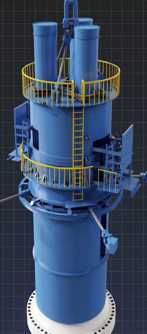
Removable Shield Blocks & Covers Lower the Radiation Level to Allow Personal Access to the Containment during Power Operation
Integrated Head Assembly & Permanent Refueling Pool Seal Simplify Refueling Works
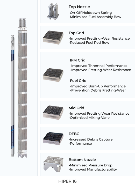
High Performance Fuel Assembly
Utilizes HIPER16™, an advanced fuel assembly with high thermal performance & enhanced seismic resistance
Provides a thermal margin greater than 10%
Increased Discharge Burn-up Enables Refueling Cycles to Be Flexible from 12 to 24 Months
Convenient Operation & Maintenance
Daily Load-Following & Frequency Control Capacity
- Enables the Plant to Respond to Power Demand Variations from the Grid
